Direct Answer
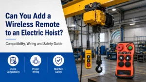
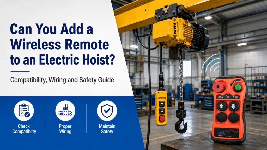
Yes. Many electric chain hoists and wire-rope hoists can be fitted with an industrial wireless remote, especially when their movements are controlled through contactors, PLC inputs or compatible drive inputs.
However, this is not a universal plug-and-play replacement.
The receiver must match the hoist’s:
- Control voltage
- Required movements
- Single- or dual-speed logic
- Output sequence
- Stop function
- Directional interlocking
- Existing pendant wiring
- Control-system architecture
Direct-control pendants, proprietary electronic controls, hazardous-area equipment and systems with safety-rated functions require project-specific review.
The modification must not bypass the hoist’s existing limit switches, overload protection, braking controls, thermal protection or other protective functions.
If you are looking for a complete transmitter and receiver solution rather than only retrofit guidance, explore our electric hoist remote control solutions for fixed hoists, powered trolleys, single- or dual-speed systems, and other industrial lifting applications.
We can help match the remote configuration according to your hoist functions, control voltage, speed logic, receiver outputs and existing wiring.
View Electric Hoist Remote Control Solutions
Author Module
Prepared by: JIAYI Industrial Remote Control Team
Technical Review: Industrial Remote Control Application Team
Last Updated: August 2026
This article provides general guidance for adding wireless control to electric hoists. Final receiver selection, wiring, inspection and commissioning should follow the actual equipment circuit, hoist manufacturer instructions and applicable local requirements.
Key Takeaways
- A wireless transmitter still requires a wired receiver connected to the hoist control circuit.
- Contactor- or PLC-controlled hoists are generally easier to retrofit than direct-control hoists.
- The receiver must match the control-circuit voltage, which may differ from the motor supply voltage.
- Button quantity alone does not determine compatibility.
- Dual-speed control may require a specific sequence of low- and high-speed outputs.
- Existing limit switches, overload protection, brakes and interlocking must remain effective.
- If valid radio communication is lost, active movement commands should be removed.
- Installation and commissioning should be performed by qualified electrical personnel.
How Does an Electric Hoist Wireless Remote Work?
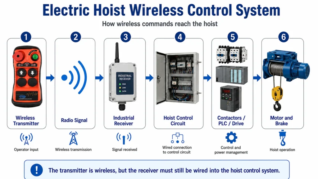
A typical wireless control system includes:
- A handheld transmitter
- An industrial receiver
- The existing hoist control circuit
- Contactors, a PLC or compatible drive inputs
- The hoist motor and brake system
The control path is:
Wireless Transmitter
→ Radio Signal
→ Industrial Receiver
→ Hoist Control Circuit
→ Contactors / PLC / Drive
→ Motor and BrakeDepending on the equipment, these outputs may command:
- Hoist up
- Hoist down
- Trolley left
- Trolley right
- Bridge forward
- Bridge reverse
- Start or enable
- Horn
- Lighting
- Auxiliary equipment
The transmitter is wireless, but the receiver must still be supplied with power and connected to the hoist control system.
A wireless retrofit is therefore not simply a matter of replacing a wired pendant with a transmitter that has the same number of buttons.
For a detailed explanation of the complete control path, read:
Crane Remote Control System: Transmitter, Receiver, Wiring and Outputs Explained
Which Electric Hoists Are Suitable for Wireless Control?
The first question is not how many buttons the new transmitter needs.
The first question is:
How does the existing pendant control the hoist?
Contactor, PLC or Drive-Controlled Hoists
In this type of system, the pendant sends relatively low-power control commands.
The motor current is handled by:
- Contactors
- A motor starter
- A PLC
- A variable-frequency drive
- Another machine-control device
These systems are generally more suitable for adding a standard industrial wireless receiver because the receiver can reproduce the pendant’s control commands.
Typical examples include:
- Workshop electric chain hoists
- Powered monorail hoists
- Wire-rope hoists
- Overhead crane hoists
- Standard material-handling systems
Direct-Control Hoists
Some small or older hoists may route motor current directly through the pendant contacts.
In this arrangement, the pendant is not only sending a low-power command. It is part of the motor power circuit.
A standard relay-output wireless receiver should not automatically be connected to this type of circuit.
A conversion may require:
- Additional contactors
- A control transformer
- A separate control enclosure
- Motor and short-circuit protection
- Revised stop and interlocking circuits
- A complete electrical redesign
A direct-control pendant should not be converted by simply connecting a standard radio receiver to the existing wires.
The current ratings and complete motor-control architecture must first be reviewed.
Systems Requiring Project-Specific Review
Additional engineering review is needed when the hoist uses:
- Proprietary electronic controls
- Safety-rated PLC functions
- Special variable-speed control
- Proportional control
- Synchronization logic
- Multiple hoists or hooks
- Explosion-protected equipment
- Unidentified or heavily modified wiring
- Manufacturer-restricted control systems
A standard relay receiver should not be assumed to be compatible with these applications.
Electric Hoist Wireless Remote Compatibility Checklist
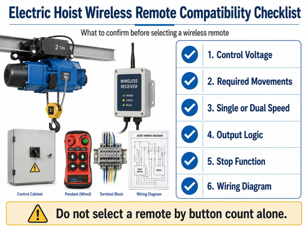
Before selecting a wireless remote, confirm the following information.
| Item | Why It Matters |
|---|---|
| Hoist type | Identifies the likely control architecture |
| Control method | Confirms whether the pendant uses direct or low-power control |
| Required movements | Determines the function and output quantity |
| Control voltage | Determines the receiver power configuration |
| Single- or dual-speed operation | Determines button stages and output sequence |
| Pendant wiring | Identifies common and directional circuits |
| Stop function | Must be coordinated with the receiver and hoist circuit |
| Output interface | May involve contactors, PLC inputs or drive inputs |
| Existing interlocking | Prevents opposing commands |
| Protective functions | Limit switches, overloads and brakes must remain active |
| Operating environment | Affects receiver protection and antenna installation |
| Required distance | Helps select the radio configuration |
| Pendant retention | Determines whether source selection is required |
Do not select a receiver by transmitter appearance or button quantity alone.
Control Voltage Is Not Always the Main Power Voltage
One of the most common retrofit mistakes is selecting the receiver according to the voltage shown on the hoist or motor nameplate.
The motor supply and control circuit may use different voltages.
For example, a hoist may have a high-voltage motor supply while its pendant, contactor coils and control transformer operate at a lower voltage.
The receiver power input must normally match the control-circuit voltage.
Where to Check the Control Voltage
The control voltage may be identified from:
- Electrical wiring diagram
- Control transformer label
- Contactor-coil label
- Existing pendant circuit
- Existing receiver label
- Control cabinet terminal markings
- Manufacturer documentation
Why Incorrect Voltage Selection Is a Problem
Choosing the wrong receiver voltage may cause:
- Failure to power the receiver
- Receiver damage
- Unstable operation
- Incorrect relay response
- Additional rewiring
- Unsafe troubleshooting attempts
Before ordering, provide the actual control voltage rather than only the hoist’s main supply voltage.
How Many Buttons Does the Remote Need?
The number of directional buttons depends on the equipment movements.
However, directional-button count does not represent the complete transmitter or receiver configuration.
| Equipment Functions | Typical Direction Buttons | Additional Controls That May Be Required |
|---|---|---|
| Fixed hoist: up/down | 2 | Start, stop or enable |
| Hoist with powered trolley | 4 | Start, stop, horn or auxiliary function |
| Overhead crane movements | 6 | Start, stop, horn, lighting or selector |
| Dual-speed equipment | 2–6 dual-stage buttons | Speed-stage sequencing |
| Customized machinery | Project-dependent | Selectors, joysticks or auxiliary switches |
Two-Direction Hoist
A fixed hoist may only require:
- Up
- Down
However, the complete system may still need a start, enable or stop function.
Hoist With Powered Trolley
A powered trolley commonly adds:
- Left
- Right
The system may therefore use four directional controls.
Overhead Crane System
A complete overhead crane may require:
- Hoist up/down
- Trolley left/right
- Bridge forward/reverse
This normally requires six directional controls, plus any start, horn or auxiliary functions.
Two transmitters with the same number of buttons may still have different output logic and may not be interchangeable.
Single-Speed vs Dual-Speed Hoist Control
Speed configuration is one of the most important details in a wireless retrofit.
Single-Speed Control
A single-speed button generally provides one operating stage.
For example:
UP Button
→ UP Receiver Output
→ Hoist Up Contactor or Drive Input
The equipment runs at one commanded speed.
Dual-Speed Control
A dual-speed button normally has two operating stages.
The first stage may command low speed, while the second stage may command high speed or another drive input.
Possible arrangements include:
- Separate low- and high-speed contactors
- Two digital inputs on a drive
- Combined relay outputs
- A low-speed output followed by a high-speed output
- Customized PLC logic
Output Sequence Matters
Dual-speed control is not always achieved by adding one independent high-speed relay.
In some systems:
- The first-stage output remains active when the second stage is pressed.
- The second stage adds another output.
- Low speed must be commanded before high speed.
- Releasing the button must remove both outputs.
- Opposing directions must remain interlocked.
In other systems, the second stage changes to a different input combination.
The wireless receiver must reproduce the original contact sequence, not simply provide two unrelated relays.
Dual Speed Is Not Proportional Control
A two-stage button normally provides two discrete commands.
It does not automatically provide:
- Proportional speed
- Stepless control
- Analog output
- CAN control
- PWM control
True proportional control requires a compatible transmitter, receiver and machine-control interface.
How Does the Receiver Connect to the Hoist?
The receiver normally connects to the control side of the hoist system.
Typical receiver connections may include:
- Receiver power input
- Common terminals
- Stop or enable outputs
- Up output
- Down output
- Left output
- Right output
- Forward output
- Reverse output
- Auxiliary outputs
These outputs may interface with:
- Contactor coils
- PLC digital inputs
- Intermediate relays
- Compatible drive inputs
- Other suitable machine-control circuits
The Receiver Is Not Automatically a Motor Contactor
A receiver relay should not be assumed to switch the main motor current directly.
Direct motor switching depends on:
- Motor voltage
- Full-load current
- Starting current
- Relay contact rating
- Load category
- Electrical protection
- Brake control
- Complete control architecture
In most industrial applications, the receiver sends operating commands to contactors, a PLC or a drive that manages the motor and brake circuits.
Direct Connection to Other Loads
Receiver outputs should not be connected directly to:
- Motors
- Brakes
- Hydraulic valves
- Solenoids
- Magnetic lifting devices
- Other inductive loads
unless the voltage, current, output type and required protection have been confirmed.
Intermediate relays or dedicated control modules may be required.
Existing Protective Functions Must Remain Effective
Adding a wireless receiver must not bypass or disable the hoist’s existing protective functions.
These may include:
- Upper limit switch
- Lower limit switch
- Overload protection
- Thermal protection
- Motor protection
- Brake control
- Contactor interlocking
- Phase protection
- Travel limits
- Drive fault inputs
- Existing stop circuit
The receiver should provide operating commands within the existing control architecture.
It should not replace protective devices that were designed specifically for the hoist.
Directional Interlocking
Opposing commands must not be active at the same time.
Typical opposing pairs include:
- Up and down
- Left and right
- Forward and reverse
Interlocking may be provided by:
- Receiver logic
- Electrical contactor interlocking
- PLC programming
- Drive logic
- A combination of these methods
Do not remove existing electrical or mechanical interlocking when installing the wireless receiver.
Stop Function Is a System-Level Requirement
A transmitter may include a red stop button.
However, the presence of a red button alone does not define the safety performance of the complete system.
The actual stop function depends on:
- Transmitter design
- Receiver stop outputs
- Relay architecture
- Contactor circuit
- Drive or PLC logic
- Brake system
- Wiring method
- Machine risk assessment
- System validation
A standard stop button should not automatically be described as:
- A certified emergency-stop function
- Safety-rated
- SIL-rated
- Performance Level-rated
unless the selected product and complete installation support those claims.
The transmitter, receiver and complete hoist control system must be evaluated together.
Can the Existing Wired Pendant Be Retained?
Some electric hoists can retain both the wired pendant and wireless control.
However, this must be treated as a dual-control-source design—not as simple parallel wiring.
Why Simple Parallel Wiring Can Be a Problem
If both control sources are active at the same time, the system may receive:
- Commands from two operators
- Opposing direction commands
- Unclear control priority
- Inconsistent stop behavior
- Unexpected movement requests
Common Source-Selection Methods
A dual-control system may use:
- Pendant/radio selector switch
- Key-operated selector
- Electrical control-source interlock
- PLC source-selection logic
- Defined command priority
- Coordinated stop functions
The objective is to ensure that only the selected or authorized source can issue movement commands.
Important Design Note
The wired pendant and radio receiver should not simply be connected in parallel without reviewing:
- Common conductors
- Directional circuits
- Stop circuit
- Electrical interlocking
- Control priority
- Recovery after power loss
- Recovery after communication loss
The appropriate arrangement depends on the existing hoist control system.
For a full comparison, see:
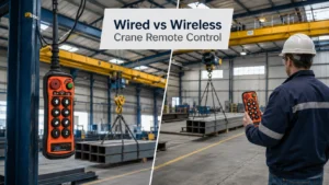
Wired vs Wireless Crane Remote Control
What Should Happen If the Radio Signal Is Lost?
The system should be designed so that loss of valid radio communication removes active movement commands rather than maintaining the last command.
How this is achieved depends on:
- Receiver relay behavior
- Contactor circuit
- PLC logic
- Drive inputs
- Stop-function architecture
- Brake system
- Installation design
Signal loss should not be treated as a substitute for the stop function or mechanical braking system.
Signal-Loss Testing
During commissioning, verify that:
- Active movement commands are removed when communication is lost.
- The hoist does not continue the last radio command.
- No direction remains unintentionally energized.
- The receiver returns to the intended state.
- Communication can be restored without unintended movement.
- A new start or enable sequence is required where applicable.
- The stop function remains effective.
Do not claim that signal loss produces an instant or zero-distance stop.
The actual stopping time and distance depend on the motor, load, brake, drive and mechanical system.
Special Applications That Require Additional Review
Hazardous or Explosion-Risk Areas
A standard industrial radio remote should not be used in a classified hazardous area unless the complete transmitter, receiver and installation are specifically approved for that environment.
An enclosure marked IP65 or IP67 is not automatically explosion-proof.
Water and dust protection ratings do not replace:
- Ex approval
- ATEX requirements
- IECEx requirements
- Other local hazardous-area approvals
Proprietary Electronic Hoists
Some hoists use manufacturer-specific electronic boards, communication buses or coded controls.
A generic relay receiver may not reproduce these commands.
The manufacturer’s interface requirements should be checked before modification.
Safety-Rated Control Systems
If the original hoist uses safety-rated control functions, adding a receiver may affect the complete safety architecture.
These projects require technical assessment and appropriate validation.
Synchronized or Multiple-Hoist Systems
Tandem or synchronized lifting is not a standard transmitter-pairing task.
It may require:
- Dedicated control logic
- Speed or position feedback
- Crane selection
- Interlocking
- Load monitoring
- Communication-state monitoring
- System-level risk assessment
Such systems should be engineered as complete applications.
Electric Hoist Wireless Retrofit Process
Installation Safety
Receiver installation and control-circuit modification should be carried out by qualified electrical personnel.
Before opening the pendant or control cabinet:
- Isolate all relevant energy sources.
- Follow the site lockout/tagout procedure.
- Verify that the relevant circuits are de-energized.
- Do not disconnect unidentified wires.
- Preserve all labels and terminal information.
- Follow the hoist manufacturer’s instructions.
Step 1: Identify the Control Architecture
Determine whether the pendant uses:
- Low-power contactor control
- PLC inputs
- Drive inputs
- Direct motor control
- Proprietary electronic control
This is the first compatibility decision.
Step 2: Record Every Required Function
List all functions, including:
- Up
- Down
- Left
- Right
- Forward
- Reverse
- Start
- Stop or enable
- Horn
- Lighting
- Auxiliary functions
Do not rely only on button count. Some buttons may have two stages or combined functions.
Step 3: Confirm the Control Voltage
Check:
- Control transformer
- Contactor coils
- Existing pendant circuit
- Electrical drawing
- Terminal labels
Do not use the motor nameplate voltage as the only reference.
Step 4: Confirm Speed Logic
Determine whether each movement is:
- Single speed
- Dual speed
- Multi-step
- Drive controlled
- Proportional
For dual-speed functions, identify the original contact sequence.
Step 5: Review the Existing Wiring
Record:
- Common terminals
- Directional conductors
- Stop or enable circuit
- Start circuit
- Speed contacts
- Interlocking
- Limit circuits
- Auxiliary functions
Take clear photographs before changing the circuit.
Step 6: Select the Receiver
Match:
- Receiver supply voltage
- Output quantity
- Relay ratings
- Output sequence
- Momentary or maintained functions
- Single- or dual-speed logic
- Stop function
- Interlocking requirements
- Environmental protection
- Antenna arrangement
Step 7: Decide Whether the Pendant Will Remain
If the pendant is retained, define:
- Source-selection method
- Command priority
- Stop-function coordination
- Interlocking method
- Recovery procedure
Step 8: Install the Receiver
The receiver should be mounted where it is:
- Mechanically secure
- Protected from impact
- Protected from excessive heat
- Protected from water and contamination
- Accessible for inspection
- Suitable for antenna performance
Avoid placing the antenna where it is heavily shielded by metal unless the selected system is designed for that arrangement.
Step 9: Perform a Static Electrical Check
Before functional operation:
- Verify receiver supply voltage.
- Check terminal labels.
- Check common and output wiring.
- Confirm no short circuit is present.
- Confirm protective devices remain connected.
- Confirm existing interlocking remains effective.
- Inspect all connections for looseness.
Step 10: Perform a No-Load Functional Test
With no suspended production load:
- Test each movement individually.
- Verify direction labels.
- Test single- or dual-speed operation.
- Check output sequence.
- Verify button release removes the command.
- Test opposing-direction interlocking.
- Confirm limit switches remain effective.
If any direction is reversed or behaves unexpectedly, stop testing and review the wiring.
Step 11: Test Stop and Communication-Loss Behavior
Verify:
- Stop-button response
- Transmitter shutdown response
- Communication interruption response
- Receiver recovery state
- Restart or enable sequence
- No unintended movement after recovery
Step 12: Complete Controlled Operational Verification
Complete final operating checks according to:
- Hoist manufacturer instructions
- Site procedures
- Local requirements
- The scope of the modification
Whether a formal inspection, test or engineering approval is required depends on the equipment and modification.
Common Mistakes When Adding a Wireless Remote
1. Selecting by Button Count Alone
The same number of buttons may represent different:
- Speed stages
- Output sequences
- Common terminals
- Auxiliary functions
- Interlocking logic
2. Confusing Main Voltage With Control Voltage
The motor supply may be different from the voltage used by the pendant and contactor coils.
3. Treating a Direct-Control Pendant as a Low-Power Pendant
A direct-control pendant may carry motor current and cannot normally be replaced by a standard relay receiver without redesign.
4. Ignoring Dual-Speed Output Sequence
Two-stage control may require a specific relationship between first- and second-stage outputs.
5. Connecting Receiver Relays to Unsuitable Loads
Receiver outputs should not be assumed to directly switch motors, brakes or other inductive loads.
6. Bypassing Existing Protective Functions
Limit switches, overload protection, brake controls and interlocking must remain effective.
7. Copying Old Wiring Without Verification
Existing equipment may have been modified and may not match the original drawing.
8. Connecting Wired and Wireless Controls Without Source Selection
Two active command sources can create conflicting requests.
9. Installing the Receiver or Antenna in a Poor Location
Metal shielding, electrical noise and unsuitable receiver placement may reduce communication reliability.
10. Failing to Test Communication Loss
Normal button operation alone does not confirm correct signal-loss behavior.
Which Wireless Remote Configuration Fits Your Hoist?
| Equipment | Typical Directional Layout | Important Checks |
|---|---|---|
| Fixed hoist | Up / down | Control method, voltage and stop function |
| Hoist with powered trolley | Up / down / left / right | Trolley interlocking and voltage |
| Overhead crane | Hoist, trolley and bridge directions | Six-direction logic and auxiliary controls |
| Dual-speed hoist | Dual-stage directional buttons | Original output sequence |
| Drive-controlled hoist | Digital or dedicated control inputs | Drive manual and input logic |
| Customized machinery | Project-specific layout | Complete control architecture |
This table provides an initial direction only.
The receiver must still be selected according to the actual control circuit.
For broader selection guidance, read:
How to Choose a Crane Remote Control for Industrial Lifting Equipment
What Information Should You Send Before Ordering?
Provide as much of the following information as possible.
Equipment Information
- Hoist manufacturer and model
- Hoist type
- Nameplate photo
- Main power supply
- Control voltage
- Indoor or outdoor application
- Operating environment
Function Information
- Required movements
- Single- or dual-speed operation
- Start or enable function
- Horn or auxiliary controls
- Simultaneous-movement requirements
- Required operating distance
Electrical Information
- Existing pendant photo
- Pendant terminal photo
- Control cabinet photo
- Wiring diagram
- Control transformer label
- Contactor-coil labels
- Existing receiver label
- Drive or PLC model
Commercial Information
- Required quantity
- Spare transmitter requirement
- OEM logo
- Custom labels
- Destination market
A wiring diagram is ideal, but several clear photographs may also help identify the control arrangement.
Do not disconnect unidentified wires only to take photographs.
Already know your hoist type, control voltage and required movements?
Compare suitable wireless remote control options for electric hoists, including push-button, single-speed, dual-speed and customized receiver configurations.
See Electric Hoist Remote Control Options
Considering a Wireless Upgrade?
JIAYI provides wireless control configurations for:
- Fixed electric hoists
- Hoists with powered trolleys
- Overhead cranes
- Gantry cranes
- Customized industrial machinery
Receiver voltage, speed logic and output functions are selected according to the actual control circuit.
Send us:
- Existing pendant photos
- Control voltage
- Required movements
- Wiring diagram
- Control cabinet photos
Our team can review the information and recommend a suitable transmitter and receiver configuration.
Explore:
JIAYI Industrial Remote Control Products
Final Recommendation
Many electric hoists controlled through contactors, PLC inputs or compatible drive inputs can be fitted with a wireless remote.
However, successful conversion depends on more than transmitter appearance or button quantity.
The correct system must match:
Control architecture + control voltage + required movements + speed sequence + receiver outputs + stop function + existing protection + wiring design.
A standard relay receiver may be suitable for a conventional contactor-controlled hoist.
A direct-control pendant, proprietary electronic hoist, hazardous-area application or safety-rated system requires additional engineering review.
Before purchasing, provide the existing pendant, control voltage and wiring information for technical confirmation.
Need Help Checking Compatibility?
Send JIAYI your:
- Hoist nameplate
- Existing pendant photos
- Control voltage
- Required movements
- Wiring diagram
- Control cabinet photos
Email: sales@jiayiremotecontrol.com
WhatsApp: +86 15705596884
Frequently Asked Questions
Can I add a wireless remote to any electric hoist?
Not every hoist can accept a standard wireless receiver. Contactor-, PLC- or compatible drive-controlled hoists are usually easier to retrofit. Direct-control pendants, proprietary electronic systems, hazardous-area equipment and safety-rated controls require additional technical review.
Does the wireless receiver need to match the hoist voltage?
The receiver must match the control-circuit voltage. This may be different from the motor or main power voltage shown on the hoist nameplate.
What is the difference between single-speed and dual-speed control?
A single-speed button normally provides one movement command. A dual-speed button has two stages and may require a specific sequence of low- and high-speed outputs. The receiver must reproduce the original control logic.
Can the wired pendant be retained?
Some hoists can keep both wired and wireless controls, but the two sources should not simply be connected in parallel. A selector switch, electrical interlock or PLC source-selection method may be required.
Does the receiver connect directly to the hoist motor?
Usually not. The receiver normally sends commands to contactor coils, PLC inputs or compatible drive inputs. Direct motor switching requires appropriate ratings, protection and a suitable electrical design.
What should happen if the radio signal is lost?
The system should remove active movement commands when valid radio communication is lost rather than maintaining the last command. The actual response depends on the receiver, contactor or drive circuit and must be verified during commissioning.